LED strobe controller to strobe a LED or machine vision light.
LED Strobe Controller features
- Small size, easy operation.
- High trigger frequency: maximum up to 50KHz.
- Short trigger response time: ≤10μs.
- Triggering modes, suitable for various work environments.
- Wide input voltage range from 12V DC to 48V DC, easy for using with the DC power supply on the machine.
- LEDs can be overdriven to increase the intensity. Please note you need a 48V powersource to overdrive a 24V ledlight.
- Wide trigger pulse width setting: 10μs ~1023ms can be set.
- Max current 2A constant output. 4A transient mode.
How to use the strobe controller?
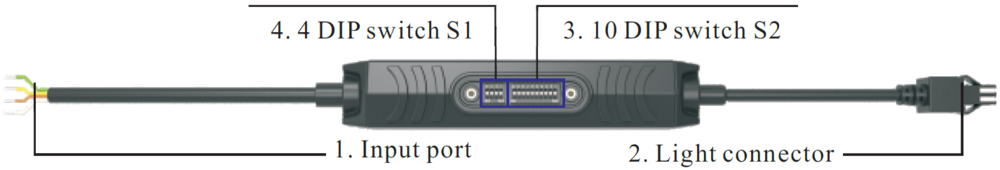
Below we explain how to use this specific strobe controller. This strobe controller has the following pinout:
Inputs pinout:
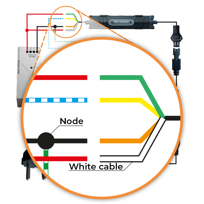
- White wire = Power+
- Brown wire = Power –
- Green wire = Trigger +
- Yellow wire = Trigger –
Output is wired to a 2 pin JST SM connector. (When removing the connector: Red wire = LED+ / Black wire = LED- )
Step 1: Program the triggerable industrial strobe controller
This strobe controller can be programmed using dipswitches, without the need of connecting the strobe controller to a pc.
The easiest way is to program the DIP switch of the industrial strobe controller for trigger on rising edge.
The position of the DIP switch S1 will set the length of the output in milliseconds or microseconds.
- In case of strobe pulse in milliseconds (11-1023ms) = dipswitch 4,3,2,1 are OFF-OFF-OFF-OFF
- In case of strobe pulse in microseconds (10-1023us) = Dipswitch 4,3,2,1 are ON-OFF-OFF-OFF (As image below)
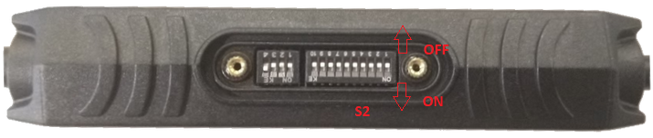
The position of DIP switch S2 of the strobe controller is for the actual duration of the pulse.
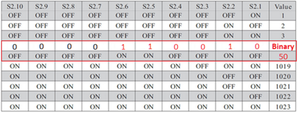
You need to set the value based on binary numbers, setting switches from right (marked S2.1) to left (marked S2.10).
Here an example how to set up the strobe for 50 microseconds: 50 in binary is 0000110010
So our switches will be set as 1=On 0=OFF ( starting from right column S2.1)
OFF ON OFF OFF ON ON, and the unused dip switches will be OFF.
Step 2: Connect the LED to the industrial strobe controller
Connecting the industrial LED light to the controller is easy plug and play. Please note that the light voltage should be 12V or 24V and consumes not more than 2A.
12V light -> you can use a standard 12V extension cable
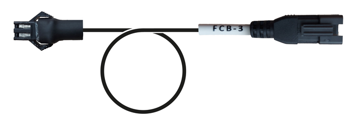
24V light -> you need to convert the 2 pin connector to a 3 pin connector using our cable 2 PIN to 3 PIN. You can than just connect the light easy
Step 3: Connect the industrial machine vision camera with the power supply and strobe controller
To connect an industrial machine vision camera you need to have an
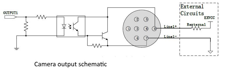
I/O cable. In our case we are using a CABLE-D-I/O-5M. We need to use the (strobe) output of the industrial vision camera to trigger the strobe controller. In our case it’s an optocoupled output called line 1 using pin 7 (Line1- White/green wire) and 8 (Line1+ White/blue wire) of the industrial vision camera
I/O connector.
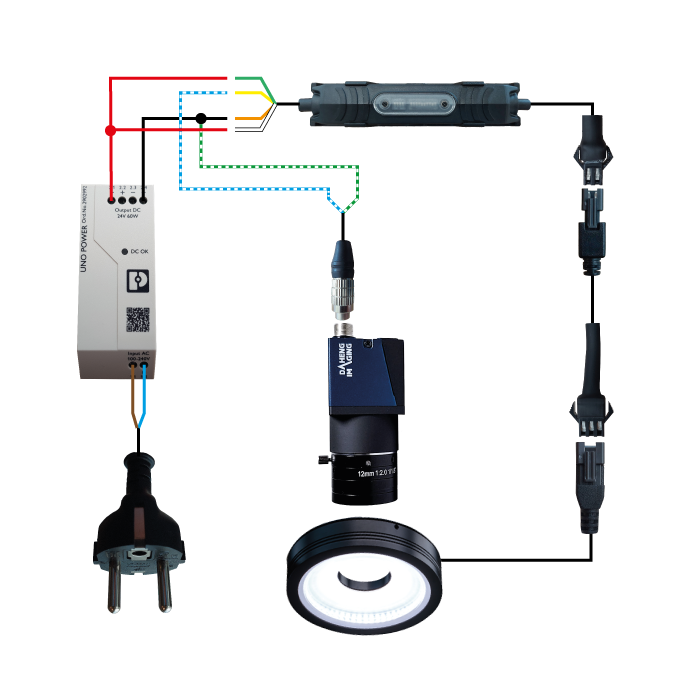
We have made a simplified drawing with the correct colours on how to connect the industrial machine vision camera, with the industrial strobe controller and the power supply.+
The
I/O cable of the industrial machine vision camera must be connected to the input port of the industrial strobe controller.
Please note that if you use a 48V powersupply with a 24V light or a
24V powersupply with a 12V light, you can overstrobe the led light. Twice the current will go through the LEDS. As a result the light intensity will be more. However the duty cycle should be less than 10% to make sure that the LEDS will not degrade fast. So in 1 second time, the LED should be max 100ms (10%) on. With a framerate of 50fps, this would mean that the led should strobe for max 2ms per image.
This is the complete schematic:
Purely as background information, the camera output schematic:
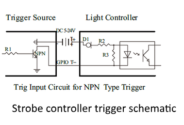
The strobe controller input schematic:
Step 4: Setup trigger and strobe settings of industrial machine vision camera
Connect the camera to the pc. Start the
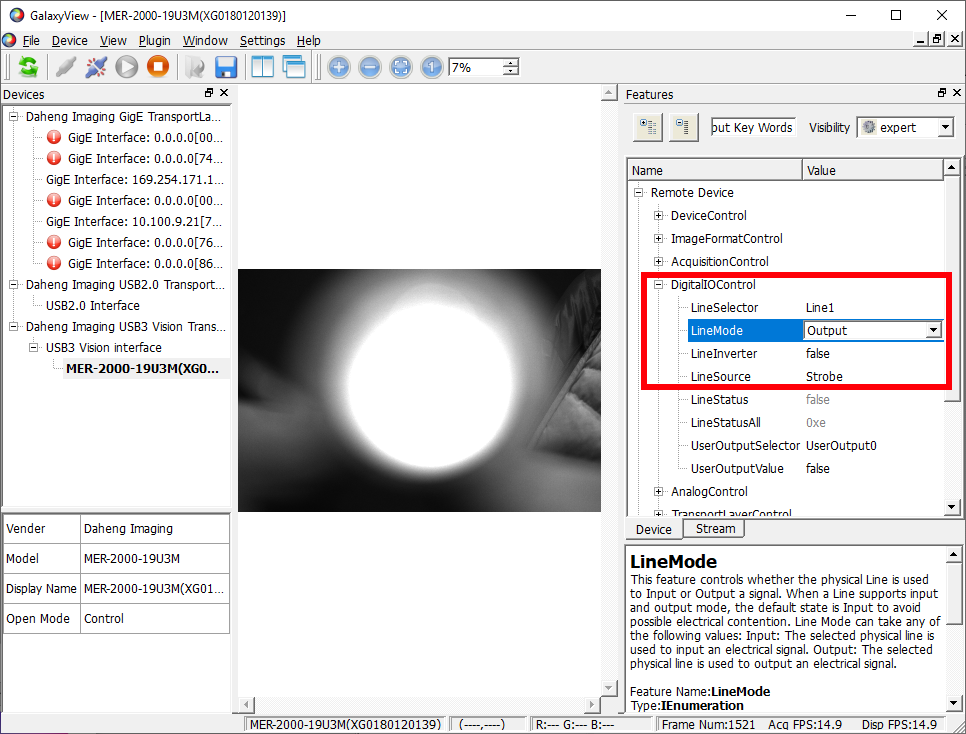
SDK (GalaxyView application when using a Daheng Imaging Camera) and connect to the industrial machine vision camera. To make the triggering working, make sure that you set the following settings (marked in the red box):
Lineselector -> line1
Linesource -> strobe
When selecting “strobe” the camera’s will output a signal to Line1 when all pixels of the camera are OPEN at the same time.
Step 5: Setup exposure time of industrial machine vision camera
Now the triggering is programmed we have to set the exposure time. For a
global-shutter industrial machine vision camera this is easy, because at exposure start all pixels are open for capturing light. Therefore any exposure time value will generate a strobe trigger pulse. For a rolling-shutter machine vision camera this is not the case.
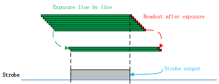
When a
rolling shutter sensor is used, the strobe output will only work during the period that all lines of the sensor are exposed (see image below). In general you can say that the minimum exposure time, for using a strobe output = 1 / (max framerate). In our example the industrial vision camera can achieve 19fps, so minimum exposure time = 1/ 19 = 52ms. After 52ms all pixel lines are ready to capture light (exposed) and you can flash. If you want to flash a LED for 1ms (Strobe output time) the calculation for the exposure time = minimum exposure time + Strobe output time) = 52ms + 1ms = 53ms.
You will notice that when you reduce for example the exposure time to 10ms, the strobe output is not working anymore, because there is no moment in time that all pixels of the rolling shutter camera are simultaneously ready to capture light.
Using an exposure time of 53ms, could mean that the industrial vision camera is also capturing light from the environment. To solve that, you have to close the iris of the lens further. To do this:
- cover up the LED.
- Then close the iris of the lens till you see a black image.
- Now uncover the LED
- Adapt the brightness of the image by closing the Iris further (when the image is over illuminated) or increase the strobe output time (when image is to dark).
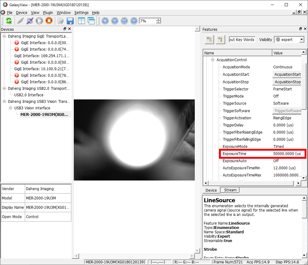
In the software of the industrial machine vision camera you can set the exposure time under AcquisitionControl->ExposureTime
Now you have a working setup, where the
industrial machine vision camera, triggers the industrial strobe controller to flash a machine vision led light.

